Voltage Detectors for 110 kV, 220 kV and 400 kV Transmission Networks
Which high-voltage detector and earthing rod do you need at 110 kV, 132/150 kV, 220 kV or 400 kV? HASEGAWA models compared by transmission voltage.
European transmission networks operate mainly at 110 kV, 220 kV and 380–400 kV, with 132 kV and 150 kV in some countries, including the United Kingdom. Taking a transmission line or a substation bay out of service at these voltages means larger clearances, longer insulating poles and a greater risk of induced voltage than on a distribution network. The rule for verifying absence of voltage does not change: every phase is tested with a detector rated for the system voltage.
This guide compares HASEGAWA high-voltage detectors and transmission line earthing rods for European transmission voltages.
Detectors by transmission voltage
| Model | Rated voltage (AC) | 110 kV | 132 / 150 kV | 220 kV | 380–400 kV | Design |
|---|---|---|---|---|---|---|
| HWB-110 | 35 – 110 kV | ✓ | – | – | – | Universal joint |
| HST-138V | 66 – 138 kV | ✓ | 132 kV only | – | – | Universal joint |
| HWB-138 | 66 – 138 kV | ✓ | 132 kV only | – | – | Universal joint |
| HST-170 | 60 – 195.5 kV | ✓ | ✓ | – | – | Hot stick, 3145 mm |
| HST-250 | 150 – 287.5 kV | – | 150 kV only | ✓ | – | Hot stick, 5055 mm |
| HWB-550 | 210 – 550 kV | – | – | ✓ | ✓ | Universal joint |
| HST-550V | 210 – 550 kV | – | – | ✓ | ✓ | Universal joint |
| HSR-500 | 250 – 550 kV | – | – | – | ✓ | Hot stick |
| HWB-550A | 11 – 550 kV | ✓ | ✓ | ✓ | ✓ | Universal joint, wide range |
Note that detectors rated up to 138 kV cannot be used at 150 kV, and HSR-500 starts at 250 kV, so it is not suitable for 220 kV.
Universal joint or hot stick?
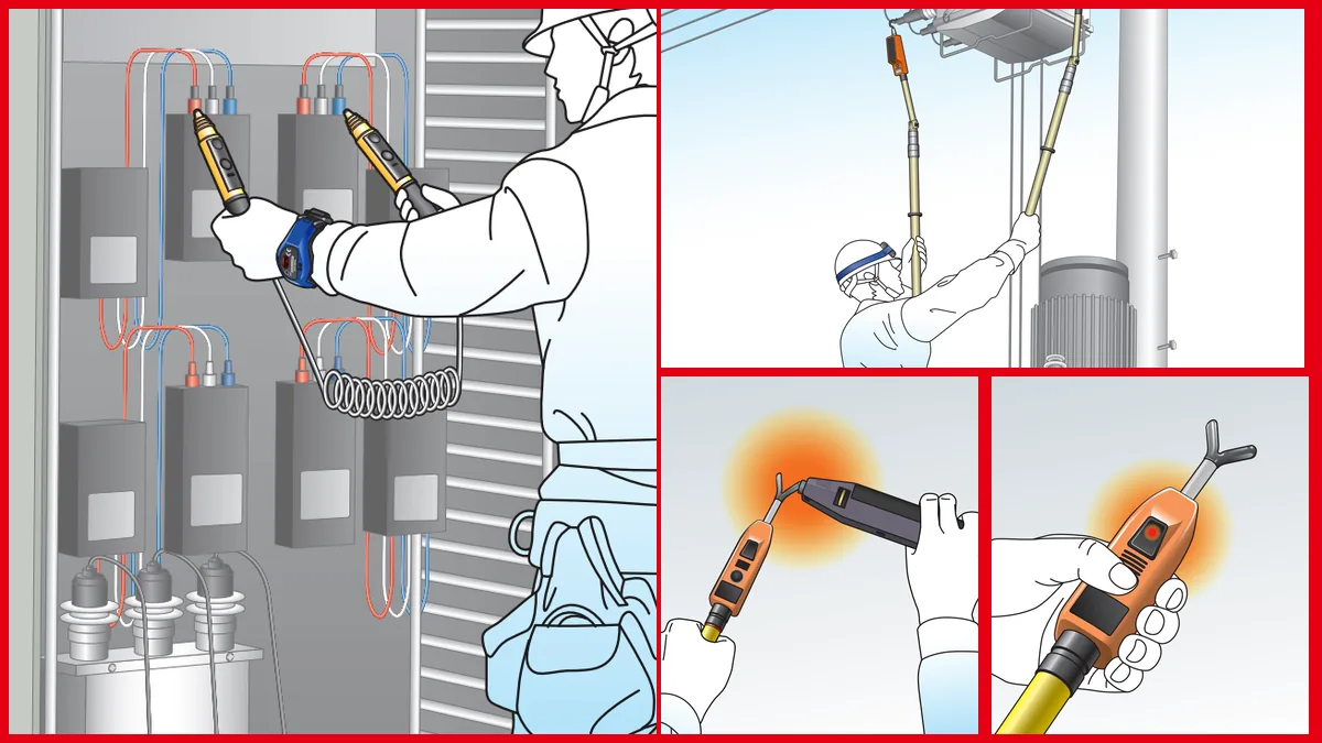
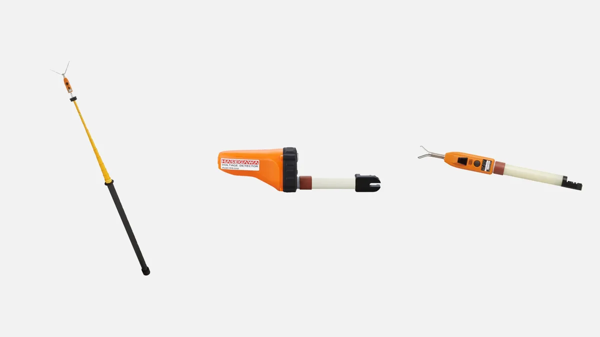
Universal-joint (separate-type) detectors fit a common insulating pole with a universal joint. Detector heads for different voltage levels can be used on the same pole, and the head can be angled towards the conductor. The HWB series has an intermittent tone of 80 dB or more, a flashing red LED that can be distinguished at 50,000 lux and water resistance equivalent to IP45, which matters in open-air substations in full sunlight.
Hot-stick detectors combine detector and insulating pole in one set. In the HST series the pole grows with the voltage: 3145 mm for HST-170 and 5055 mm for HST-250. The 400 kV-class HSR-500 is dielectric-tested at 15 points along its insulating pole and weighs about 4.5 kg.
One detector for a whole substation: HWB-550A
Where 400 kV, 220 kV, 110 kV and medium-voltage bays share a substation, carrying a detector for each level is costly and invites mistakes. HWB-550A covers 11 kV to 550 kV with one instrument. A green LED shows standby and switches off automatically after about two minutes; a flashing red LED and intermittent tone indicate voltage.
Transmission line earthing rods
Once absence of voltage is confirmed, the line must be earthed and short-circuited on both sides of the work location. HASEGAWA telescopic earthing rods are short for transport and long in use:
| Model | Voltage class | Extended length | Retracted length | Earthing cable |
|---|---|---|---|---|
| Type Z1 | 275 kV | 4.0 m | 1.8 m | 22 mm² × 5 m |
| Type Z2 | 154 kV | 2.6 m | 1.5 m | 22 mm² × 4 m |
| Type Z3 | 77 kV | 1.5 m | – | 22 mm² × 3 m |
| Type Y2 | 154 kV | 2.5 m | 1.4 m | 22 mm² × 4 m |
| Type Y3 | 77 kV | 1.5 m | 0.9 m | 22 mm² × 3 m |
Type Z rods lock by compression, Type Y rods by push button. For 110 kV to 150 kV lines, the 154 kV class (Type Z2 or Type Y2) applies; for 220 kV, the 275 kV class (Type Z1). If your bays need specific clamps, pole lengths or cable cross-sections, our custom earthing equipment can be built from 6.6 kV to 275 kV. We assess 400 kV earthing requirements individually at the quotation stage. When ordering, state the prospective fault current and its duration so that the cable and clamps can be specified to IEC 61230; see Standards & Compliance.
Verifying absence of voltage at transmission level
- Right detector, right pole. The detector's range must include the system voltage, and the pole length must keep you at the minimum approach distance in your procedures.
- Check the detector before and after. Use its self-test, a suitable tester or a known live source (the live–dead–live principle).
- Test every phase and conductor. On double-circuit lines and bundled conductors, test every conductor you will work on.
- Beware of induced voltage. A dead line next to live circuits can carry induced voltage, which is why earthing must follow immediately after verification.
- Weather. Rain and humidity increase surface leakage on insulating poles; keep them clean and dry and do not work outside the manufacturer's limits.
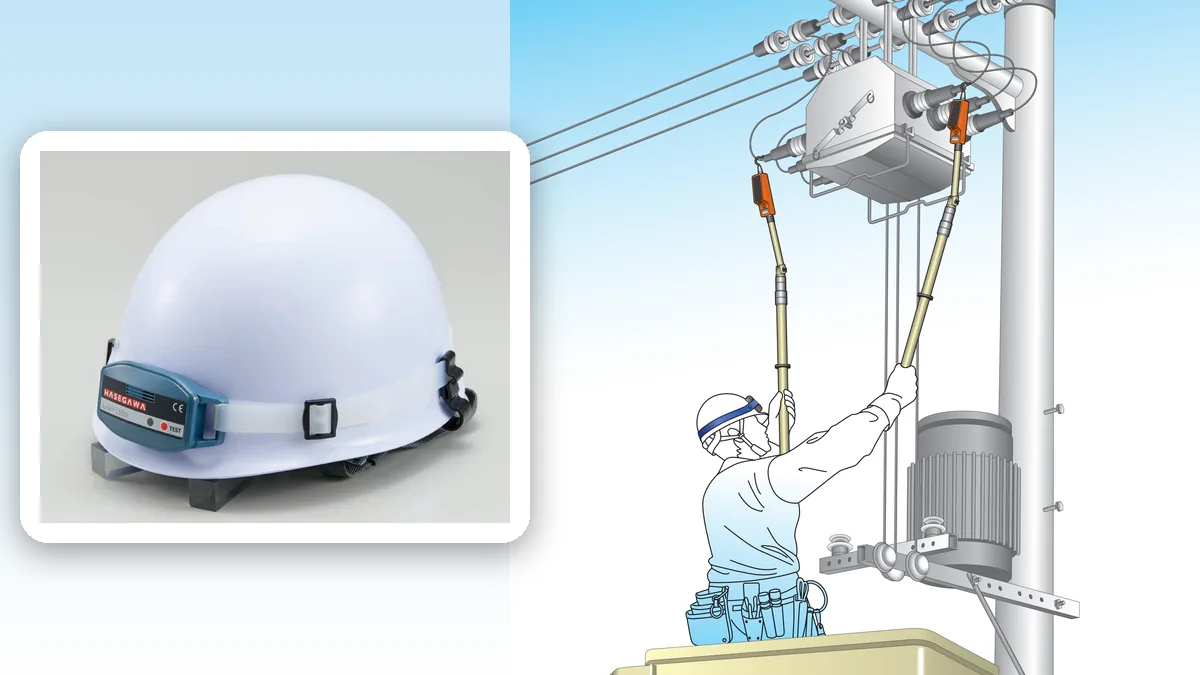
For teams working near live lines up to 110 kV, HXA-70 arm and HXA-70S helmet proximity alarms (66–110 kV) add an extra warning.
Frequently Asked Questions
Which voltage detector is suitable for 400 kV?
HWB-550, HST-550V (210–550 kV), HSR-500 (250–550 kV) or the wide-range HWB-550A. The bay layout and the pole length you need decide between them.
Which detector should I use on a 132 kV or 150 kV line?
HST-170 (60–195.5 kV) and HWB-550A cover both. HST-138V and HWB-138 cover 132 kV but not 150 kV; HST-250 covers 150 kV but not 132 kV.
Can one detector test both 20 kV and 400 kV?
Yes, HWB-550A, which works from 11 kV to 550 kV. The other models have narrower ranges.
Which earthing rod class do I need for a 220 kV line?
The rod's voltage class must be equal to or above the line voltage, so for 220 kV the 275 kV class Type Z1.
Planning a transmission project in Europe? Send us your voltages and bay types through the quote form. For the regulatory background, read Electrical Safety at Work in Europe.