Safe Working in Medium-Voltage Switchgear: A Step-by-Step Guide
Isolation, locking off, voltage verification, cubicle earthing, discharging residual charge and arc precautions in MV switchgear, with a checklist table and the most common mistakes.
Safe working in medium-voltage (MV) switchgear means isolating and locking off the cubicle from every direction that can feed it, verifying the absence of voltage at the point of work with a suitable MV voltage detector, then earthing and short-circuiting the cubicle and protecting against busbars or adjacent cubicles that remain live. An open circuit-breaker, or indicator lamps on the cubicle going out, does not by itself mean "dead". At distribution voltages such as 20 kV or 33 kV, even a small error in the sequence can lead to an arc flash and a fatal accident.
In this article we cover the steps to follow before maintenance or cable termination work in an MV cubicle, a checklist table, stored charge and arc risk, and the most common mistakes on site. The general framework is the five safety rules for work in a de-energised state, as set out in EN 50110-1; here we focus on what those rules mean inside the switchgear.
What should be prepared before working in MV switchgear?
- Written instructions and permit-to-work: UK HSE guidance HSG85 recommends that on high-voltage systems an electrical permit-to-work is issued, but only after all dead-working precautions have been taken. Before issuing the permit, the authorised person should work out in writing the steps to disconnect, isolate, prove dead, lock off and earth the equipment. Where switching is carried out by remote control, make sure the instructions exchanged are clearly understood.
- Single-line diagram: Mark every direction from which the cubicle can be fed (ring circuit, standby supply, bus coupler, generator, backfeed through a voltage transformer).
- Competence: The ISSA Electricity Section's guidance on the five safety rules calls for a nominated person responsible for the installation and a nominated person in control of the work activity, both competent for the planned work. HSG85 describes "authorised persons" appointed by the employer, preferably in writing, on the basis of training, experience and knowledge of the system.
- Equipment: A voltage detector and tester suited to the network voltage, an earthing set suited to the cubicle type, a discharge stick where needed, locks and warning notices, insulating gloves and PPE appropriate to the arc risk.
Safe working in MV switchgear, step by step
1. Switching and isolation
First the current is interrupted with the circuit-breaker (or load-break switch), then the disconnector is opened to provide a reliable isolating gap. HSG85 calls for isolation by a device that provides a safe isolating gap between live parts and the parts made dead. In withdrawable switchgear, the circuit-breaker is racked out to the test/disconnected position. If the cubicle can be fed from more than one direction, each supply point is isolated separately. Disconnector operations are carried out with an insulated operating rod suited to the voltage class.
2. Lock-out and tag-out (LOTO)
The operating mechanisms and controls of the opened circuit-breaker and disconnector are locked, and notices such as "Do not switch – work in progress" are posted. Remote control (SCADA) is disabled. HSG85 recommends safety locks with unique keys, with the keys retained in a key safe or other place available only to the person in charge of the work. Where several people are working, a multi-lock hasp or lock box ensures that the installation cannot be energised until the last lock has been removed.
3. Voltage testing: how is it done in MV switchgear?
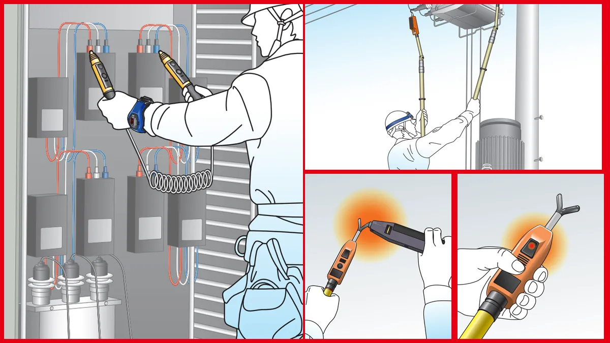
The absence of voltage is verified at the point of work and on all three phases. Points to watch:
- Indirect signs are not trusted. A meter reading zero, lamps going out or a transformer falling silent do not prove the dead state. HSG85 states that parts should be proved dead even if isolation has been achieved automatically through an interlocking system.
- The cubicle's voltage detecting and indicating system (VDIS) gives the first information. These systems are defined in IEC 62271-213. However, if your organisation's procedure requires verification with a portable detector, this step is not skipped.
- The detector must suit the network voltage. The reference for capacitive MV detectors is IEC 61243-1. The 2021 edition assumes the detector is used in contact with a bare conductor; on painted or coated surfaces the coating can behave like a capacitor and cause an incorrect indication. The check should therefore be made at a bare contact point on the busbar or cable termination.
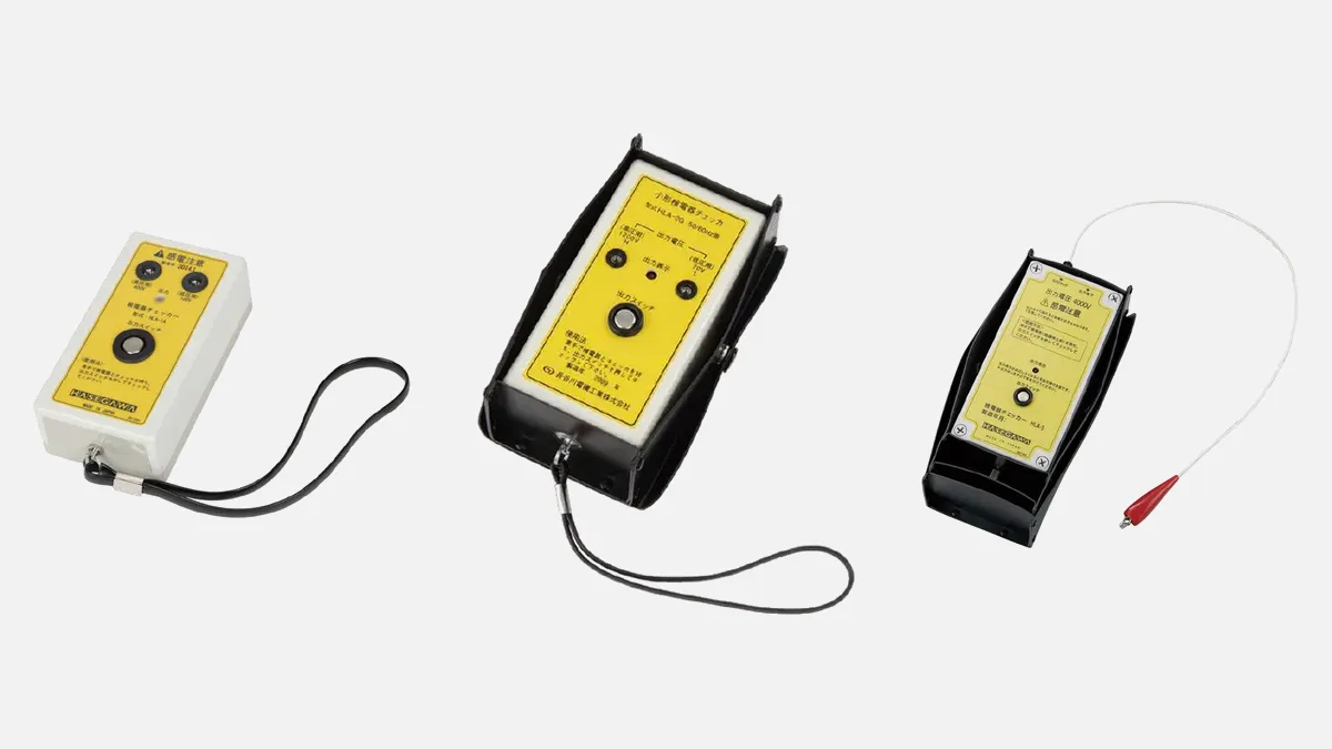
- The detector is tested before and after use. This check, with a tester or a known live source, prevents a faulty detector from giving a false "no voltage" result.
We discuss detector selection in detail in how to choose a voltage detector.
4. Cubicle earthing and short-circuiting
As soon as the absence of voltage has been verified, the cubicle is earthed. In practice there are two routes:
- If the cubicle has a cable-side or busbar earthing switch that earths the section being worked on, closing it can provide the required earthing.
- If the fixed earthing switch cannot earth the other devices in the cubicle, portable earthing and short-circuiting devices are connected to suitable bare connection points in the cubicle or on the devices.
When using a portable cubicle earthing set, the set is connected first to the installation's earth bar, then to the three phases with an insulated stick. HSG85 states that, on high-voltage equipment, earthing conductors at the point where the supply is disconnected are essential and additional earths may be necessary at the place of work; the earthing and short-circuiting device should also be visible from the work location. The earths remain in place throughout the work. For details on set selection, cross-section and clamps, see our earthing sets article.
5. Stored charge and residual voltage
MV cables and capacitors can hold charge after the supply has been disconnected. Earthing therefore protects not only against accidental re-energisation but also against stored charge. After a cable withstand test (DC or VLF), or in cubicles with a capacitor bank, residual charge is drained in a controlled way with a suitable discharge stick, after which the earths are applied. If the earths need to be removed temporarily for testing, HSG85 notes that this should be done under a clearly defined sanction-to-test procedure.
6. Protection against parts that remain live
Even with the circuit-breaker open, the cubicle busbars may still be live because the rest of the installation is in service. Use the switchgear's segregation, shutters or insulating barriers as the manufacturer intends; where the busbar compartment is not segregated and adequate protection cannot be provided, the busbars should also be made dead. HSG85 recommends physical barriers and/or temporary insulation, with danger notices, to protect against inadvertent contact with nearby live parts. Adjacent cubicles and live parts are marked with warning notices and barriers.
MV switchgear checklist
| Step | Check | Equipment | Common mistake |
|---|---|---|---|
| Preparation | Permit-to-work, single-line diagram, all supply directions | Permit-to-work form | Forgetting the ring or standby supply |
| Isolation | Circuit-breaker open, disconnector open / truck racked out | Operating rod | Opening only the circuit-breaker |
| Locking | Lock, notice, remote control disabled | Padlock, multi-lock hasp, notice | Leaving the key in the panel |
| Voltage test | At a bare point, on all three phases; detector tested before/after | MV detector, tester | Trusting the VDIS lamp or a coated surface |
| Earthing | Earth first, then phases; close to the work location | Cubicle earthing set | Reversing the earth/phase sequence |
| Residual charge | Cables and capacitors discharged | Discharge stick | Skipping discharge after testing |
| Adjacent parts | Busbar segregation, shutters, barriers | Barrier, insulating cover, notice | Approaching a live busbar |
What should you watch for regarding PPE and arc risk?
Because high voltage can arc across an air gap, electric shock or burns can occur without touching a conductor; HSG85 makes this point explicitly. Operations such as voltage testing and earthing inside the cubicle are therefore carried out on the assumption that the parts may be live. Insulating gloves and an insulating mat are recommended against shock; where an arc risk cannot be eliminated, adequately rated flame-retardant clothing providing thermal protection, together with face and eye protection, is recommended. The international reference standard for arc protective clothing is IEC 61482-2. The required level of protection should be determined by a site-specific risk assessment.
What not to do in MV switchgear
- Opening the cubicle door without seeing the circuit-breaker and disconnector positions and without locking them.
- Checking for voltage only by looking at the cubicle front panel or indicator lamps.
- Using a detector of unknown voltage class, or one that has not been tested.
- Connecting the earthing set to the phase first, or leaving the earths far from the work location.
- Touching a cable termination after a cable test without discharging and earthing it.
- Working in a non-segregated cubicle without protection against the live busbar.
- Removing the earths before the work is finished and before all workers have been informed. The ISSA guidance on the five safety rules requires that all workers have reported completion and been told the permit is cancelled before earths are removed, and that as soon as one safety measure is cancelled, all de-energised parts are regarded as live.
Which HASEGAWA equipment is used in MV switchgear?
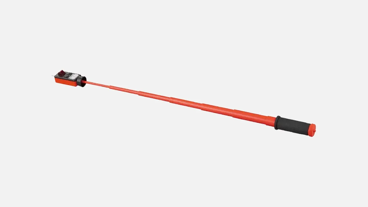
For voltage testing on distribution networks in the 36 kV class, the HASEGAWA HSS-36B1 medium/low-voltage detector, operating in the range AC 80 V – 36 kV, can be used; note that it does not detect low voltage in stick-extension mode. To test MV detectors before use, the HLA-3 voltage detector tester, which generates a test voltage of AC 4000 V, is suitable. For the earthing step, cubicle earthing sets including the Type H, Type HA-W, Type HC and Type HF models are used, and discharge sticks for residual charge on cables and capacitors. The cross-section of the earthing set should be selected according to the short-circuit current of the installation.
Related guides: the five safety rules for electrical work, IEC 61243-1 voltage detector standard.
Frequently Asked Questions
How is voltage testing carried out in MV switchgear?
With an MV voltage detector suited to the network voltage and tested before use, on a bare conductor at the point of work, checking each of the three phases separately. The detector is tested again at the end.
Is closing the cubicle's earthing switch enough?
Closing the cable-side or busbar earthing switch can provide the required earthing if it earths the section being worked on. If it does not earth the part to be worked on, a portable cubicle earthing set should be fitted at the work location.
Are the voltage indicator lamps on the cubicle sufficient?
Indicating systems provide valuable first information, but they can fail, and indirect signs should not be relied on as proof of the dead state. If your organisation's procedure requires it, verify with a portable detector.
Why is discharge needed after a cable test?
During a withstand test the cable becomes charged, and it can retain a dangerous charge after the test source is disconnected. Do not touch the cable termination until this charge has been drained with a discharge stick and the cable has been earthed.
If you would like help selecting detectors, earthing sets or discharge sticks for your MV switchgear, contact us via the quote form.
Sources
- HSE – HSG85 Electricity at work: Safe working practices (3rd edition, 2013)
- ISSA Electricity Section / BG ETEM – Five Safety Rules: Working in a de-energised state (leaflet)
- IEC 61243-1:2021 – Live working, Voltage detectors, Part 1: Capacitive type
- IEC 62271-213:2021 – Voltage detecting and indicating system (VDIS)
- IEC 61482-2 – Protective clothing against the thermal hazards of an electric arc
- DEHN – Safe Working on Electrical Installations: Earthing and Short-Circuiting Devices (DS191/E)